company

How to Use FCAW in Welding for Stronger Welds?

Fabrication shops need welds that survive vibration, impact, and changing temperatures. Fcaw In Welding offers a practical route to that reliability, especially on structural steel, heavy equipment, and outdoor repairs. Its continuously fed tubular wire deposits metal quickly and tolerates certain surface conditions better than many manual processes. However, speed alone does not create a stronger joint. Joint design, travel angle, electrical settings, and slag removal still control the final result.

Industry data supports careful process selection. The U.S. Bureau of Labor Statistics projects about 42,600 annual openings for welders, cutters, solderers, and brazers from 2023 through 2033. That demand reflects the continuing need for skilled production and maintenance work. The American Welding Society also identifies workforce development and welding quality as major industry concerns in its welding workforce reports. In practice, this means FCAW operators need more than machine familiarity. They need repeatable procedures, inspection awareness, and documented parameter control.

The arc tells the truth.

A clean-looking bead may still contain porosity, lack of fusion, or trapped slag. This is where FCAW can disappoint inexperienced users. Excessive stickout, poor grounding, or incorrect shielding gas may weaken a weld that appears attractive. A thoughtful procedure should follow applicable requirements, such as AWS D1.1 for structural steel, while considering the wire classification and base-metal thickness. This guide explains how FCAW works, how professionals tune it, and how inspection can confirm stronger weld performance. Some results will vary. That limitation deserves attention.

How to Use FCAW in Welding for Stronger Welds?

Understanding FCAW Equipment, Materials, and Welding Fundamentals

How to Use FCAW in Welding for Stronger Welds?

Understanding FCAW Equipment, Materials, and Welding Fundamentals

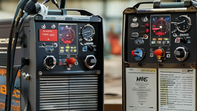
Flux-cored arc welding uses a tubular wire filled with flux-forming compounds. The equipment needs a constant-voltage power source, wire feeder, welding gun, work clamp, and suitable shielding system. Self-shielded FCAW supports outdoor work because it produces protective gases internally. Gas-shielded FCAW usually delivers cleaner welds in controlled conditions. Always verify polarity against the wire classification. A wrong setting can create unstable arcs and trapped slag.

Material preparation decides more than many beginners expect. Remove oil, paint, heavy rust, and moisture from the joint. Carbon steel, low-alloy steel, and stainless steel require different consumables and procedures. Match wire classification, diameter, shielding gas, and plate thickness carefully. Adjust wire-feed speed, voltage, travel speed, contact-tip-to-work distance, and gun angle together. The American Welding Society projects a U.S. shortage of 330,000 welding professionals by 2029, increasing the value of disciplined training and inspection. In my shop experience, a bright bead can still hide incomplete fusion. I check the toes, root, and slag removal before trusting appearance. Keep a steady travel rhythm. Pause slightly at the joint edges. Excessive speed often leaves a narrow, weak profile. Excessive heat can enlarge the weld and distort thinner plate. Review the procedure after each test weld, because small parameter changes can expose weaknesses.

Preparing the Joint, Work Area, and Welding Parameters

FCAW produces strong welds only when preparation matches the procedure. I inspect the joint before touching the torch. The bevel must be consistent, the root gap controlled, and every edge free from rust, paint, oil, and moisture. Poor fit-up forces excessive heat and increases distortion. A dry wire and clean liner also matter. I have seen attractive beads fail because the root was never properly opened.

The work area needs equal attention. Remove combustible materials, secure the workpiece, and confirm a reliable return connection. OSHA 29 CFR 1910.252 specifies mechanical ventilation when a welder has less than 10,000 cubic feet of workspace. NIOSH’s welding-fume guidance also emphasizes local exhaust near the arc. Keep airflow controlled, however. Strong drafts can disturb shielding gas. That mistake is easy to miss.

Set voltage, wire-feed speed, polarity, travel speed, and electrode extension from the qualified welding procedure. Do not copy a parameter from another joint without checking thickness and position. FCAW manufacturers’ procedure data commonly shows that small voltage changes alter bead shape and penetration. I still make a short test weld when conditions change. A parameter table is not a guarantee. Watch the arc, listen for an even sound, and measure the finished profile. Remove slag completely between passes. Incomplete cleaning can hide trapped discontinuities during visual inspection. (OSHA, 29 CFR 1910.252; NIOSH, Criteria for a Recommended Standard: Welding, Brazing, and Thermal Cutting)

How to Use FCAW in Welding for Stronger Welds?

Preparing the Joint, Work Area, and Welding Parameters

The chart shows typical operating current windows for gas-shielded FCAW on mild steel using common wire diameters in flat or horizontal welding positions. The actual setting must follow the electrode classification, joint design, welding position, shielding-gas condition, and qualified WPS.

  • Prepare the joint by removing rust, paint, oil, moisture, and mill scale from the weld area.
  • Keep the work area dry and protected from drafts that can disturb shielding gas.
  • Control voltage, wire feed speed, travel speed, and contact-tip-to-work distance to maintain a stable arc and consistent penetration.

Setting the Correct FCAW Technique for Stronger Welds

Setting the correct FCAW technique begins with the joint, wire type, and welding position. I inspect the groove for oil, moisture, mill scale, and loose rust. Even a small contaminant can create porosity or weak fusion. The wire specification must match the base metal and shielding method. Gas-shielded FCAW and self-shielded FCAW require different settings and handling.

I set voltage and wire feed speed within the recommended range, then test on scrap steel. A stable arc should sound crisp, not harsh or irregular. I keep the electrode extension consistent, usually around 15 to 25 millimeters, depending on the wire and procedure. The gun angle stays near 10 to 15 degrees in the travel direction. Too much angle can trap slag and reduce penetration. Short, controlled movements usually produce a cleaner bead.

Watch the puddle closely. It reveals more than the machine display. I adjust travel speed when the bead becomes narrow, convex, or uneven. After each pass, I remove slag completely with a chipping tool and wire brush. A missed slag pocket may remain hidden until inspection. I have sometimes trusted an attractive surface too quickly; that was a mistake. Weld quality also depends on fit-up, preheating requirements, interpass temperature, and the welder’s consistency. Record the settings, but do not follow them blindly when joint conditions change.

Managing Heat, Slag, and Weld Bead Quality During Welding

How to Use FCAW in Welding for Stronger Welds?

FCAW can produce strong welds when heat, slag, and bead shape remain under control. Before welding, I check the material thickness, joint fit-up, wire size, polarity, and recommended procedure. Excessive heat may cause distortion, undercut, or burn-through. Too little heat can create poor fusion and trapped slag. I watch the puddle closely, not only the machine settings. A bright, steady arc helps me judge whether travel speed and voltage need adjustment.

Slag control is equally important. After each pass, I remove slag with a chipping hammer and wire brush. Even small flakes can hide inclusions between layers. I keep the electrode angle consistent and maintain a short, controlled arc. The weld bead should have smooth edges, suitable width, and even ripples. A bead that looks attractive may still lack fusion. That is easy to forget.

Tips: Clean the joint before welding. Follow the qualified welding procedure. Keep the gun angle near the recommended range. Adjust travel speed when the bead becomes tall, narrow, or uneven. Watch for excessive spatter. It often signals unstable settings or poor technique. On thicker joints, allow suitable interpass cooling and inspect every layer. I sometimes want to weld faster, but rushing can trap slag. My own results improve when I pause, clean carefully, and inspect the bead before continuing. A small defect deserves attention.

Inspecting and Improving FCAW Weld Strength and Consistency

How to Use FCAW in Welding for Stronger Welds?

Inspecting and Improving FCAW Weld Strength and Consistency

Strong FCAW welds begin with controlled preparation, not appearance alone. Clean the joint thoroughly, remove oil, rust, paint, and loose scale. Check fit-up, root gap, and alignment before striking the arc. Small variations can create large stress points. Use the qualified welding procedure for wire type, polarity, current, voltage, travel speed, and preheat requirements. Record these settings during production. A stable arc and consistent stick-out often produce a more predictable bead.

Inspect every pass after removing slag. Look for undercut, overlap, cracks, visible porosity, excessive convexity, and uneven tie-in. A bright, smooth surface can still hide incomplete fusion. Do not assume. For critical work, approved non-destructive testing may be needed. Visual inspection is useful, but it has limits. I have seen operators chase a perfect profile while ignoring poor joint cleaning. That judgment deserves reconsideration.

Tips: Keep the contact-tip-to-work distance consistent. Maintain the recommended gun angle and travel direction. Use short, steady movements instead of forcing wide weaves. Remove all slag before the next pass. Check wire storage and liner condition when feeding becomes erratic. Watch the puddle, not only the arc. If porosity appears, stop and investigate shielding, wind, moisture, and surface contamination. Make one change at a time, then inspect the result. A simple weld log can reveal patterns that memory misses. During final inspection, measure bead size and compare it with the procedure, rather than relying on visual confidence.

How to Use FCAW in Welding for Stronger Welds? – Inspecting and Improving FCAW Weld Strength and Consistency

Inspection or Process Dimension Recommended Control or Typical Range Effect on Weld Strength and Consistency Inspection Method or Acceptance Focus Common Problem Indicator Improvement Action
Welding Process Use FCAW with the electrode and shielding method specified by the approved welding procedure. FCAW may be self-shielded or gas-shielded. Correct process selection supports adequate penetration, deposition efficiency, and resistance to cracking. Confirm the procedure, electrode classification, polarity, and shielding arrangement before welding. Incorrect electrode, polarity, or shielding setup. Verify the procedure and perform a controlled setup check before production welding.
Wire Diameter Common FCAW wire diameters include approximately 0.045 in, 1/16 in, and 5/64 in, depending on joint thickness and position. Wire diameter affects deposition rate, current demand, bead size, and control in different welding positions. Check wire size against the approved procedure and visually inspect the wire for rust, damage, or contamination. Oversized bead, unstable arc, or poor positional control. Use a smaller diameter for thinner material or positional work when permitted by the procedure.
Welding Current Use the qualified procedure range. A typical starting range for many structural FCAW applications is about 150–300 A, but the correct value depends on wire size and joint design. Insufficient current can cause incomplete fusion; excessive current can increase spatter, undercut, and distortion. Record actual amperage and compare it with the procedure range during welding. Cold lap, inadequate penetration, excessive spatter, or undercut. Adjust current in small steps while maintaining the specified travel speed and voltage.
Arc Voltage Use the procedure-qualified voltage range. Many FCAW applications operate approximately between 22 and 32 V, depending on wire size, shielding, and position. Voltage influences arc length, bead width, penetration profile, and spatter level. Monitor voltage at the power source or wire feeder and confirm stable arc behavior. Long, erratic arc, excessive spatter, convex bead, or porosity. Correct voltage gradually and check that the contact-tip-to-work distance remains consistent.
Travel Speed Maintain a steady speed appropriate for the joint and procedure. Excessively slow travel increases heat input; excessive speed can reduce fusion. Consistent travel speed produces a uniform bead profile and more predictable heat-affected-zone behavior. Observe bead width, reinforcement, penetration, and continuity; record travel speed when required. Irregular bead width, burn-through, undercut, or incomplete fusion. Use a steady travel rhythm and practice on representative material before production welding.
Contact-Tip-to-Work Distance Follow the electrode manufacturer's procedure requirements. For many FCAW applications, approximately 19–32 mm is a common working range. Distance changes electrode extension, current delivery, arc stability, and penetration. Measure or visually control the distance during setup and monitor it during welding. Unstable arc, inconsistent penetration, or excessive spatter. Keep the torch position and distance steady; replace worn contact tips.
Shielding Gas For gas-shielded FCAW, use the specified gas and flow rate. A common flow range is approximately 15–25 L/min, subject to procedure and site conditions. Correct shielding protects the molten pool from atmospheric contamination and reduces porosity. Check gas type, flow rate, leaks, regulator condition, and drafts around the weld area. Pinholes, internal porosity, unstable arc, or excessive oxidation. Repair leaks, remove drafts, clean the gas nozzle, and reset the flow rate.
Polarity Use the polarity specified for the selected FCAW electrode. Gas-shielded and self-shielded wires may require different polarity arrangements. Incorrect polarity can cause poor arc stability, excessive spatter, and inadequate fusion. Verify cable connections and polarity before striking the arc. Erratic arc, poor bead shape, low deposition efficiency, or lack of fusion. Stop welding and correct the polarity before making additional welds.
Joint Preparation Keep the groove angle, root opening, root face, and alignment within the qualified procedure limits. Consistent joint geometry allows predictable penetration and reduces the risk of incomplete fusion. Use gauges and visual inspection before welding; remove excessive mismatch and contamination. Uneven penetration, excessive reinforcement, lack of side-wall fusion, or burn-through. Correct fit-up and tack welds before depositing the production weld.
Surface Cleanliness Remove oil, moisture, paint, loose scale, rust, and other contaminants from the weld area. Clean surfaces reduce hydrogen-related problems, porosity, inclusions, and arc instability. Perform a visual check before welding and between passes; ensure the joint is dry. Porosity, wormholes, slag entrapment, or delayed cracking. Clean mechanically or chemically as appropriate and preheat when required by the procedure.
Interpass Cleaning Remove all visible slag and spatter between passes using an approved chipping tool, wire brush, or mechanical method. Prevents slag inclusions and supports reliable fusion between successive weld layers. Inspect each pass before depositing the next pass; pay special attention to toes and corners. Linear indications, trapped slag, lack of fusion, or irregular bead overlap. Clean thoroughly and correct the bead sequence or torch angle if slag repeatedly remains trapped.
Torch Angle and Manipulation Maintain a consistent travel angle and work angle suited to the joint. Avoid excessive weaving unless permitted by the procedure. Stable torch control improves side-wall fusion, bead shape, and penetration consistency. Observe the arc position, bead edges, and overlap during each pass. Uneven toes, side-wall undercut, lack of fusion, or irregular reinforcement. Use a narrower, controlled technique and maintain the arc at the leading edge of the weld pool.
Heat Input Control heat input according to the qualified procedure. A commonly used calculation is: heat input = voltage × amperage × 60 ÷ travel speed. Heat input affects cooling rate, distortion, toughness, residual stress, and heat-affected-zone properties. Calculate and record heat input when required; verify preheat and interpass temperature. Excessive distortion, soft or brittle heat-affected zone, or inconsistent mechanical results. Adjust current, voltage, or travel speed within qualified limits rather than changing several variables at once.
Preheat and Interpass Temperature Follow the welding procedure and material requirements. Temperature depends on composition, thickness, restraint, and hydrogen control. Proper temperature control reduces rapid cooling and lowers the risk of hydrogen-assisted cracking. Measure with calibrated temperature indicators, contact thermometers, or approved infrared equipment. Cold cracking, delayed cracking, or excessive hardness near the weld. Raise or maintain temperature as specified and protect the joint from moisture and rapid cooling.
Visual Inspection Inspect the completed weld for continuity, profile, size, undercut, overlap, cracks, arc strikes, and visible porosity. Early detection prevents defective welds from progressing to later fabrication stages. Use adequate lighting, weld gauges, magnification when needed, and qualified acceptance criteria. Any visible crack, unacceptable undercut, undersized weld, or incomplete weld length. Repair only under an approved repair procedure and re-inspect the repaired area.
Non-Destructive Examination Use methods such as liquid penetrant, magnetic particle, ultrasonic, or radiographic testing when required by the application or specification. Detects surface or internal discontinuities that cannot be confirmed by visual inspection alone. Select the method according to material, joint type, thickness, discontinuity risk, and acceptance criteria. Relevant indications, volumetric defects, planar flaws, or crack-like signals. Evaluate indications against the applicable acceptance criteria and perform controlled repair if permitted.
Mechanical Verification When qualification or production testing is required, use tensile, bend, impact, hardness, or macroetch testing as applicable. Confirms that weld strength, ductility, toughness, and fusion meet the required performance level. Test representative weld samples using calibrated equipment and documented procedures. Bend opening, tensile failure through the weld, excessive hardness, or incomplete fusion revealed by macroetch. Review variables, consumable control, fit-up, and welder technique before requalification or production restart.
Consumable Storage Keep FCAW wire clean, dry, protected from damage, and stored according to the consumable procedure. Moisture and contamination can contribute to porosity, hydrogen-related cracking, and unstable feeding. Inspect packaging, storage conditions, wire surface, and exposure history. Rusty wire, feeding resistance, porosity, or inconsistent arc behavior. Remove compromised consumables from service and improve storage and handling controls.
Documentation and Traceability Record procedure identification, welder identification, material, consumable, parameters, preheat, interpass temperature, and inspection results. Traceability makes recurring defects easier to identify and supports consistent production quality. Review welding logs and inspection records for completeness and parameter compliance. Unexplained variation, missing records, or repeated defects with no clear cause. Use a standard welding data sheet and investigate trends rather than isolated defects only.

Note: The numerical ranges shown are typical starting references, not universal settings. Final values must be established and controlled through the applicable qualified welding procedure, material requirements, joint design, welding position, and acceptance criteria.