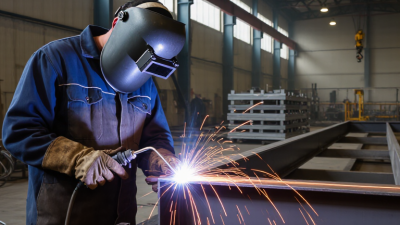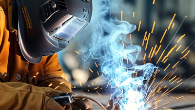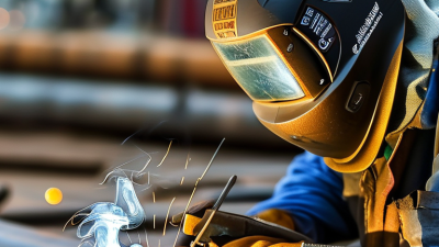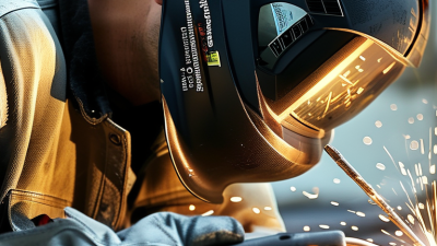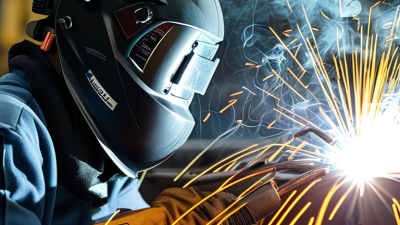
Fcaw In Welding refers to flux-cored arc welding, a process that feeds tubular wire through a welding gun to create a continuous arc. The wire’s flux helps protect the molten weld pool, while the finished bead often carries a layer of slag. Some wires also require external shielding gas; others are designed for use without it. The distinction matters. Wire type, polarity, voltage, and feed speed must match the manufacturer’s instructions and the job’s approved procedure.
This guide explains how to prepare equipment, choose suitable settings, and make controlled welds on common steel applications. You’ll see why clean, properly fitted joints matter, and how gun angle, travel speed, and stickout affect bead shape. A steady hand helps, but setup matters just as much. Too much stickout can make the arc unstable; moving too quickly may leave a narrow, inconsistent bead. Small changes show up fast.
Practice on scrap of similar thickness before welding a finished part. Inspect the work under good lighting, and remove slag between passes where required. FCAW can be productive, especially on thicker material, but it is not foolproof. I’ve seen a weld look acceptable at a glance and still need closer inspection. Use appropriate protective equipment, maintain ventilation, and follow the wire maker’s guidance and applicable workplace procedures. The sections ahead cover the practical steps, common problems, and checks that help produce sound, repeatable welds.
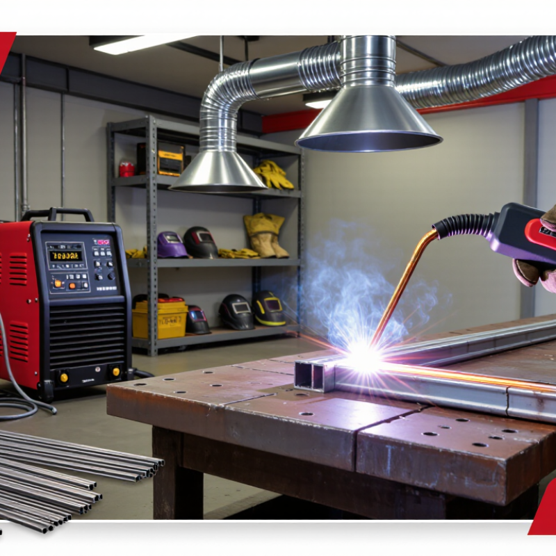
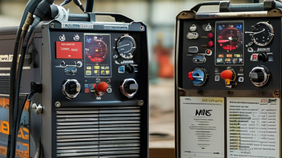
FCAW uses a continuously fed tubular wire filled with flux. The basic setup includes a power source, wire feeder, welding gun, and work clamp. The wire feeds through the gun as the arc melts it and the base metal. Keep it steady. A stable feed helps maintain a more consistent bead.
Some FCAW wires create their own shielding gas, while others require external gas and a cylinder. Check the wire specifications before setting up, because polarity and shielding requirements can vary. Wear a welding helmet, gloves, and protective clothing, and ensure the work area has suitable ventilation.
Clean rust, oil, and paint from the joint; contamination can cause porosity or uneven welds. Small details matter. Set voltage and wire-feed speed for the wire diameter, material thickness, and joint, then test on scrap of similar thickness.
Watch the arc, listen for a steady sound, and inspect the bead for gaps or excessive spatter. The first pass may still look uneven, even with careful setup. That’s a useful signal to pause and adjust rather than assume one setting fits every job.
Before FCAW, clean the joint until bare, sound metal is visible. Remove oil, paint, rust, and dampness that could contaminate the weld. A wire brush may loosen scale, but heavy coatings need more thorough removal. Check the edges for cracks or laminations. They can hide beneath a clean-looking surface. Set the bevel, root gap, and alignment to match the joint design or approved welding procedure. Clamp the work firmly, then confirm the work lead has a clean metal contact. Small gaps matter.
Choose flux-cored wire for the base-metal type, thickness, welding position, and required strength. Confirm whether the wire is designed for gas shielding or self-shielding; they are not interchangeable. For gas-shielded wire, check the specified gas and flow, and watch for drafts that can disturb coverage. Match polarity to the wire manufacturer’s instructions. Keep the spool dry and free of dirt, and check that the drive rolls and contact tip suit the wire diameter. They should feed smoothly. A useful habit is to test settings on scrap of similar thickness before welding the actual joint. I still double-check polarity; it is easy to overlook when changing wire. Keep ventilation effective, especially when coatings or confined spaces are involved.
Before striking an arc, match the FCAW wire to the base metal, joint, and welding position. Check its data sheet for polarity and starting voltage and wire-feed settings; flux-cored wires do not all use the same setup. Fit the correct drive rolls and contact tip, then check that the wire feeds smoothly. Set stickout to the wire maker’s guidance. Small details matter.
Prepare the work area before switching on the welder. Clear paper, solvents, and other combustible material from the work zone, and keep a suitable fire extinguisher nearby. Use welding screens to protect people from arc flash. Wear a welding helmet, gloves, flame-resistant clothing, and eye protection. Ventilation matters, especially with gas-shielded FCAW; keep your head out of the fume plume. If using shielding gas, secure the cylinder upright and check its connections for leaks.
Clamp the work lead to clean metal close to the joint, not to a painted or rusty surface. Arrange cables so they cannot snag underfoot, and inspect them for damaged insulation. Make a short test weld on scrap of similar thickness. Look for steady feeding, consistent bead shape, and excessive spatter. A clean setup can still make a rough first bead. Treat it as feedback: change one setting at a time, and note what improved—or did not.
A sound FCAW bead starts before the arc. Clean off oil, rust, and loose scale, then clamp the joint firmly. Check the procedure for wire type, polarity, voltage, and wire-feed speed; these settings are not interchangeable. Run a short test bead on similar scrap. Keep the contact-tip-to-work distance steady, and use the travel angle specified for the wire. Small changes matter.
AWS’s Welding Handbook, Volume 2, describes FCAW deposition rates reaching roughly 25 pounds per hour in suitable high-current, flat-position conditions. Treat that figure as a process capability, not a speed target. A hurried pass can leave poor fusion or trap slag.
Watch the leading edge of the puddle, not just the bright arc. Move evenly, and avoid weaving wider than the procedure allows. Between passes, remove slag completely and inspect the bead for cracks, undercut, or trapped inclusions. A neat surface can still conceal a weak root; I have learned not to judge quality by appearance alone.
Fume control matters, too. IARC Monographs, Volume 118, classifies welding fumes as carcinogenic to humans, Group 1. Use effective local exhaust and suitable protective equipment, and keep your head out of the plume.
If the arc sounds erratic, pause and check the ground, wire feed, and settings before changing several things at once.
After an FCAW pass has cooled enough for safe inspection, remove the slag with a chipping tool and wire brush. Wear eye protection; sharp slag can fly farther than expected. Examine the full bead under bright light, including both toes and the start and stop points. Look for a consistent profile, sound tie-in, and visible cracks. Small details matter.
Porosity may appear as pinholes or clusters of round cavities. Undercut looks like a groove beside the weld toe, while overlap leaves metal rolled onto the base material without proper fusion. Slag inclusions can hide beneath an irregular bead. A smooth surface does not prove a sound weld. That assumption is easy to make.
Relate each defect to the process before attempting a repair. Check whether the joint was clean, the travel angle was steady, and the wire feed and voltage matched the approved procedure. Wind or poor shielding can contribute to porosity; excessive travel speed may leave an uneven bead. These clues are useful, but not conclusive. Record what you find, and use specified nondestructive testing when the application requires it. Remove defects only with an approved repair method, then reinspect the area. Sometimes the cause is still unclear. Revisit the setup rather than simply covering the flaw with another pass.
| Defect or Check | What to Look For | Common FCAW-Related Causes | Inspection Method | Practical Corrective Action |
|---|---|---|---|---|
| Porosity | Round cavities or pinholes visible on the weld surface; internal pores may not be visible. | Contamination, damp or unsuitable consumables, inadequate shielding, excessive electrode extension, or drafts affecting gas-shielded FCAW. | Clean the weld and perform visual examination. Use radiographic or ultrasonic examination when required by the inspection plan. | Remove affected weld metal as required, clean the joint, check shielding and wire handling, then reweld using the qualified procedure. |
| Slag Inclusion | Slag trapped on the surface or between weld passes; may appear as a linear indication during nondestructive examination. | Incomplete slag removal, poor joint access, incorrect bead placement, or an unsuitable travel angle or technique. | Inspect after removing slag from each pass. Apply radiographic or ultrasonic testing where specified. | Remove slag thoroughly between passes. Excavate confirmed defects to sound metal and reweld in accordance with the approved procedure. |
| Lack of Fusion | Incomplete bonding between weld metal and base metal, or between adjacent weld passes. | Insufficient heat input, excessive travel speed, incorrect torch angle, poor joint preparation, or failure to direct the arc into the joint sidewall. | Check the weld profile and accessible surfaces visually. Use an appropriate volumetric examination when required; visual inspection alone cannot confirm internal fusion. | Verify procedure settings and joint preparation. Remove unfused material and reweld using the approved technique and parameters. |
| Undercut | A groove along the weld toe that remains unfilled by weld metal. | Excessive travel speed or current, incorrect electrode angle, or poor control of the weld pool. | Visually examine the weld toes; use a weld gauge when profile measurement is required. | Adjust technique and settings within the qualified procedure. Repair the groove when required by the applicable acceptance criteria. |
| Overlap | Weld metal rolls onto the base metal without blending smoothly at the toe. | Slow travel, excessive deposition, low heat relative to deposition rate, or an unsuitable electrode angle. | Visual examination of both weld toes and the weld profile. | Correct travel speed, angle, and deposition technique. Remove unacceptable overlap and restore the weld profile as required. |
| Cracking | Linear discontinuities in the weld metal or heat-affected zone; cracks may be visible at the surface or occur internally. | Hydrogen, rapid cooling, high restraint, unsuitable consumable handling, or an unqualified welding sequence or procedure. | Visual examination, with magnetic-particle or liquid-penetrant testing for surface-breaking cracks where appropriate. Use additional methods when specified. | Stop and report the finding. Determine the cause, remove the crack completely, and repair only under an approved repair procedure. |
| Excessive Spatter | Numerous droplets adhering around the weld; spatter can obscure inspection or interfere with fit-up and coating. | Unstable arc, incorrect voltage or wire-feed settings, poor grounding, or unsuitable stickout and travel technique. | Visual examination after cleaning; confirm that the weld surface and adjacent areas remain inspectable. | Check connections and settings against the welding procedure. Remove spatter where necessary without damaging the base metal or weld. |
| Final Visual Inspection | Check weld size, length, location, profile, toe transitions, surface condition, and completion of required passes. | Missed inspection stages, incomplete slag removal, inconsistent bead placement, or failure to compare the weld with the drawing and procedure. | Use adequate lighting and visual aids or gauges as needed. Record findings and identify any areas requiring further examination. | Compare results with the governing code, project specification, and approved welding procedure. Document and resolve nonconformities before acceptance. |
| Acceptance note: Defect limits and repair requirements vary by application, material, joint type, and governing code or project specification. Do not treat this table as a substitute for the approved welding procedure or inspection criteria. | ||||