How to Understand Welding Rod Purpose and Types?
Understanding Welding Rod Purpose begins with a practical question: what must the weld endure after the arc disappears? A rod is not merely a metal stick. Its coating, core composition, diameter, and strength affect penetration, bead shape, slag removal, and resistance to cracking. Welding educator Jody Collier explains, “Choosing the right electrode begins with understanding the job, not memorizing rod numbers.” That principle remains useful on a dusty workshop floor.
Different rods serve different conditions. An E6010 rod can dig deeply into dirty steel and suit demanding root passes. An E6013 rod usually creates a smoother arc for lighter fabrication. E7018 rods provide strong, low-hydrogen welds, but their storage matters. Damp flux can quietly damage weld quality. It happens.
This guide will connect Welding Rod Purpose with rod classifications, base-metal compatibility, welding positions, amperage, and jobsite preparation. You will see how a rod behaves when the joint is vertical, the steel is rusty, or the machine feels underpowered. Real welding rarely follows a perfect chart. Fit-up changes. Technique varies. Even experienced welders can choose poorly when they rush. That uncomfortable truth deserves attention.
The goal is not to memorize every electrode code. It is to read the code, inspect the material, test the arc, and verify the finished bead. A clean-looking weld can still hide weak fusion. Sound judgment matters more than confident guesses. Welding safely also requires proper ventilation, protective equipment, and instruction from qualified professionals.
Define Welding Rods: Electrodes, Filler Metals, and Their Core Purposes
How to Understand Welding Rod Purpose and Types?
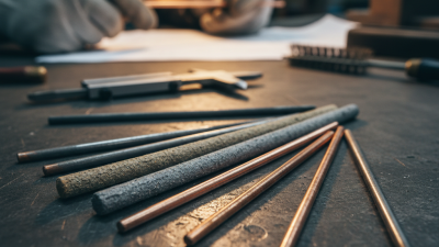
Welding rods are commonly called electrodes, but the terms are not always identical. An electrode carries electrical current through the arc. Some electrodes also melt and become filler metal. A coated stick electrode performs both jobs, creating an arc while depositing metal into the joint. Other electrodes, such as tungsten electrodes, mainly maintain the arc and do not normally become part of the weld. The word “rod” is imperfect, but practical welders still use it daily.
Filler metal has a different core purpose: it fills the joint and shapes the weld bead. It may come from a stick electrode, a separate wire, or a straight rod used with an external heat source. Selection depends on the base metal, joint design, thickness, welding position, and required strength. In practice, a thin sheet may need a smaller diameter and controlled heat. A heavy joint may require multiple passes. Too much filler can trap slag or create an uneven profile. That detail is easy to overlook.
Tips:
Check the electrode classification, storage condition, and recommended current range before welding. Keep the arc length consistent, and watch the molten pool rather than only the bright arc. A clean joint matters. Rust, paint, oil, and moisture can cause porosity or weak fusion. Even experienced operators should verify the procedure, because a familiar rod may behave differently on an unfamiliar alloy. One assumption can be costly.
Decode AWS Classifications: What E6010, E7018, and E308L Mean
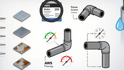
Understanding AWS welding classifications helps you choose a rod for strength, position, and metal chemistry. In each code, “E” means electrode. In E6010, “60” indicates 60,000 psi minimum tensile strength, while “1” means all-position welding. The final “0” identifies its coating and current characteristics. E6010 usually creates a forceful arc, deep penetration, and a fast-freezing slag. It is useful for root passes and dirty steel, but it demands steady arc control.
E7018 follows a similar pattern. “70” means 70,000 psi minimum tensile strength, and “1” again means all positions. The “8” identifies a low-hydrogen, iron-powder coating and related current options. Keep these electrodes dry. Moisture can increase hydrogen-related cracking risk, especially in restrained joints. The arc feels smoother than E6010, and the slag often peels away in broad sections. That description is practical, not absolute; machine settings and storage still change results.
E308L belongs to stainless-steel electrode classifications, so its numbers work differently. “308” describes the deposited stainless chemistry, while “L” means lower carbon content. This helps reduce carbide precipitation during welding and supports corrosion resistance in suitable stainless applications. The ending, such as “-16,” adds coating and operating information. Do not select a rod from strength numbers alone. Check the base metal, service temperature, joint restraint, polarity, and qualified welding procedure. I have seen acceptable-looking beads fail after cooling because fit-up and cleaning were neglected. Small details matter.
Match Rod Types to Welding Processes, Metals, and Joint Positions
A welding rod is not just a filler metal. Its coating controls the arc, shielding, penetration, and slag. Match the rod to the welding process, base metal, and joint position. For example, E6010 produces a forceful arc and deep penetration, making it useful for open-root pipe joints with direct current. E6011 offers similar penetration and can operate with alternating current. It often handles rusty or lightly contaminated steel better, though surface cleaning remains safer.
E6013 creates a softer arc and a neat bead, which suits thin mild steel and flat or vertical work. E7018 provides strong, low-hydrogen welds for clean structural steel. Keep it dry, because moisture can increase cracking risks.
For cast iron, nickel-based rods are often more suitable than ordinary steel electrodes. Stainless steel also needs a compatible stainless electrode. A mismatch may look acceptable but fail under vibration or heat.
Tips:
Check the electrode classification, polarity, amperage range, and position rating before striking an arc. Practice on a scrap piece first. Watch the puddle, not only the sparks. Joint fit-up matters. Even an excellent rod cannot rescue a wide, uneven gap. I sometimes prefer a slower travel speed, but that choice can overheat thin metal. Recheck the bead after cleaning slag, especially at the toes and root.
Compare Electrode Strengths: 60 ksi for E6010 and 70 ksi for E7018
How to Understand Welding Rod Purpose and Types?
Electrode numbers are practical clues, not decoration. According to AWS A5.1/A5.1M, E6010 deposits weld metal with a minimum tensile strength of 60 ksi, or about 415 MPa. E7018 reaches 70 ksi, or about 485 MPa. The first two digits describe strength. The third indicates welding positions. The final digit identifies coating and current characteristics.
Strength alone does not decide the correct rod. E6010 commonly produces a forceful arc and deep penetration, useful for root passes and imperfect fit-up. Its cellulose coating creates a gaseous shield and a narrow, digging arc. E7018 uses a low-hydrogen coating with iron powder. It offers a smoother arc, heavier deposition, and better control on structural joints. AWS guidance on low-hydrogen electrodes also stresses dry storage and proper rebaking procedures. Moisture can increase hydrogen-related cracking risk.
That difference matters at the workbench. A 60-ksi E6010 root may bite through a tight joint, while a 70-ksi E7018 cap can leave a flatter, cleaner bead. Still, 70 ksi does not automatically mean a safer weld. Procedure qualification, base-metal chemistry, preheat, heat input, and welder technique govern the final result. I once focused too heavily on tensile strength. That was incomplete. AWS Welding Handbook guidance repeatedly links weld quality to fit-up, cleanliness, and controlled technique. Field inspection should confirm the joint’s required strength, toughness, and defect limits through qualified procedures and suitable testing. Numbers help. They do not replace judgment.
Understanding Welding Rod Purpose and Types
The first two digits in an AWS electrode classification indicate the minimum tensile strength in thousands of pounds per square inch (ksi). E6010 provides a minimum tensile strength of 60 ksi, while E7018 provides 70 ksi. E6010 is commonly selected for deep penetration and root passes, whereas E7018 is commonly used when higher strength and low-hydrogen welding performance are required.
Choose Rod Diameters from 1.6–6.4 mm and Apply Proper Storage Practices
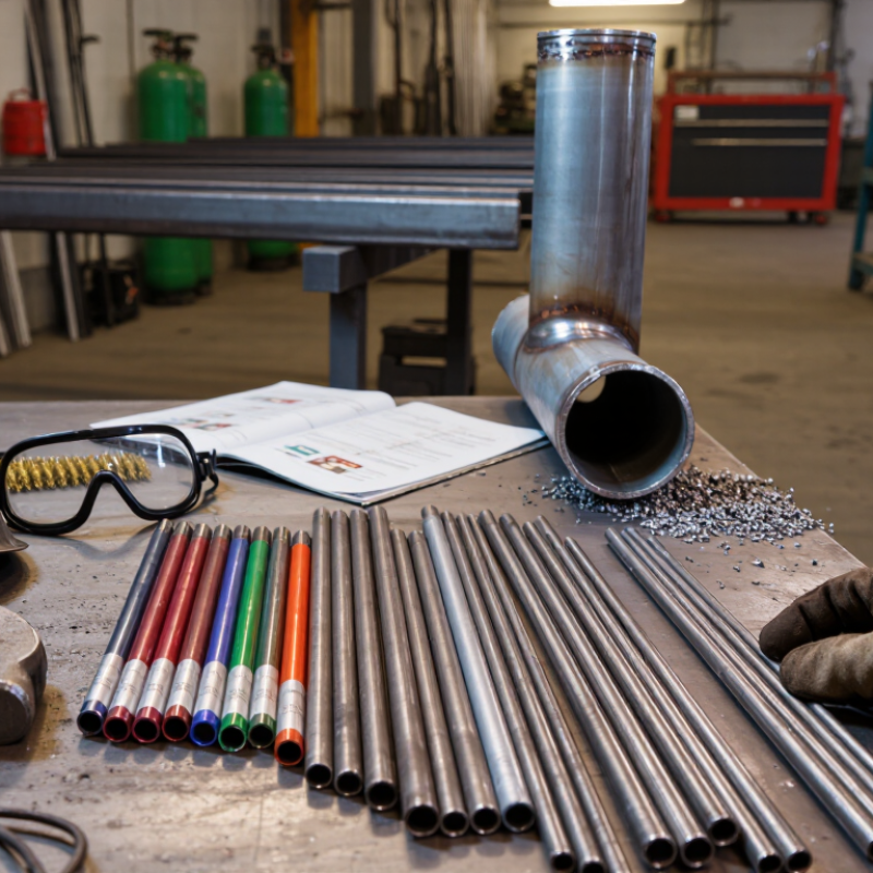
Welding rod diameter controls current demand, bead size, and penetration. Thin 1.6 mm rods suit light sheet and small repair joints when heat must stay low. Use 2.0 or 2.5 mm rods for general fabrication, tack work, and moderate plate thickness. A 3.2 mm rod carries more heat and deposits metal faster on prepared joints. Choose 4.0, 5.0, or 6.4 mm only when the machine, joint, and material can accept higher current. Coating type matters too. Rutile rods provide easy starts, while low-hydrogen rods require stricter moisture control. Do not select by diameter alone. Position, gap, coating, and welding direction also matter.
Storage protects the coating, which strongly affects arc stability and weld quality. Keep unopened rods in a dry, clean cabinet, away from concrete floors, rain, oil, and sudden temperature changes. After opening, follow the stated holding temperature and time for that electrode type. Use a heated holding oven when the welding procedure requires it, and record opening dates. Never trust a damp box. Moisture can cause spatter, porosity, poor arc starts, or cracking in sensitive welds. Store small working quantities in covered containers, not loose in a toolbox. That shortcut feels harmless.
In workshop practice, I match rod size to the thinnest section, available amperage, and welding position. A large rod may fill a groove quickly, yet it can overheat a thin edge or create an uneven bead. For overhead work, a smaller diameter often gives better control, even if it requires more passes. Clean the joint to bright metal, then make a short test bead on similar scrap. Inspect fusion, undercut, pores, and bead profile before continuing. I still sometimes choose a larger rod too quickly. That mistake costs time. Written procedures, current readings, and a dry electrode log make the next choice more reliable.
How to Understand Welding Rod Purpose and Types? - Choose Rod Diameters from 1.6–6.4 mm and Apply Proper Storage Practices
| Rod Diameter |
Typical Current Range* |
Suitable Material Thickness |
Common Uses |
Practical Selection Guidance |
| 1.6 mm |
20–45 A |
About 1.5–3 mm |
Light sheet metal, tack welds, small repairs, and low-heat work |
Helps reduce burn-through when used with short arcs and controlled travel speed |
| 2.0 mm |
35–65 A |
About 2–4 mm |
Thin mild-steel components, brackets, frames, and maintenance work |
A useful step up from 1.6 mm when slightly more deposition is needed |
| 2.5 mm |
60–90 A |
About 3–6 mm |
General-purpose fabrication, fillet welds, gates, frames, and repairs |
Often selected for routine work because it balances control and deposition rate |
| 3.2 mm |
90–130 A |
About 5–10 mm |
Structural joints, medium-to-heavy fabrication, and multi-pass welds |
Requires adequate heat input and joint preparation to achieve proper fusion |
| 4.0 mm |
130–180 A |
About 8–14 mm |
Heavy sections, large fillet welds, and production fabrication |
Use only when the power source and workpiece can safely accept higher heat input |
| 5.0 mm |
180–250 A |
About 12–20 mm |
Heavy structural work and large-volume weld deposits |
Usually applied in multiple passes; check welding procedure requirements before use |
| 6.4 mm |
240–330 A |
Above 16 mm |
Very heavy sections, large joints, and high-deposition applications |
Needs a suitably rated power source, careful heat control, and qualified procedures |
*Note: Current ranges are typical starting points for many mild-steel coated electrodes. The exact setting depends on electrode classification, coating type, welding position, joint design, power source, and the electrode manufacturer's technical data.
| Rod Type or Classification |
Primary Purpose |
Typical Polarity or Current |
Common Welding Positions |
Storage Considerations |
| E6010 |
Deep penetration on clean and moderately contaminated mild steel; root passes and pipe work |
Usually direct current electrode positive, depending on the approved procedure |
All positions |
Keep dry and protected from moisture; follow the product data sheet for conditioning requirements |
| E6011 |
Deep-penetrating repair and maintenance welding where alternating current may be needed |
Alternating current or direct current electrode positive, subject to the classification and procedure |
All positions |
Store in a dry location and prevent coating damage or contamination |
| E6013 |
Smooth, easy-to-use general fabrication on mild steel with light-to-moderate penetration |
Alternating current or direct current, depending on the electrode specification |
All positions, with size limitations for vertical and overhead work |
Keep sealed or dry; discard electrodes with cracked, flaking, or contaminated coatings |
| E7018 |
Low-hydrogen structural welding where strength and resistance to hydrogen-assisted cracking are important |
Usually direct current electrode positive; some products are approved for alternating current |
All positions, subject to electrode diameter and procedure limits |
Keep sealed until use; after opening, store in a heated holding oven or recondition only as specified by the applicable standard or product data sheet |
| E7024 |
High-deposition fillet and groove welds on mild steel |
Alternating current or direct current electrode positive, as specified |
Primarily flat and horizontal fillet positions |
Protect from humidity and use dry electrodes with intact coatings |
| Stainless-steel covered electrodes |
Joining or repairing stainless steel; select the classification to match the base metal and service conditions |
Often alternating current or direct current electrode positive, depending on classification |
Position capability varies by classification and diameter |
Keep dry, clean, and separated from carbon-steel consumables to reduce contamination risk |
Recommended Storage Practices
- Keep unopened electrodes in their original sealed packaging in a clean, dry, temperature-controlled area.
- Store opened electrodes above the floor and away from water, oil, chemicals, direct sunlight, and large temperature changes.
- Use the oldest suitable package first and mark opened packages with the opening date.
- Do not use electrodes with damp, cracked, swollen, or flaking coatings.
- Low-hydrogen electrodes require stricter exposure control; use the holding temperature and maximum exposure time stated in the applicable welding procedure or product data sheet.
- Choose the diameter according to joint thickness, welding position, required deposition rate, available current, and permitted heat input—not thickness alone.